GE 70 Tonner
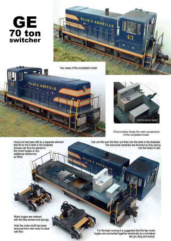
GE 70 Tonner
|
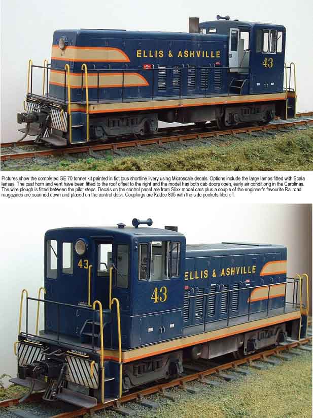
This O scale 1/48th kit release is based on the American GE 70 ton prototype introduced in the 1940’s. It makes a model of the early variant without the grill on the hood front. Many are still in active service on short lines, industry and in preservation in the USA. The completed model shown has been motorised using
Slaters Low-mac wheels, ref. 7130, Mashima 14:24 motor (2mm shaft),
Romford 40:1 gears (1/8th axle, 2mm worm) plus Delrin 1/8th, 8 toothed
sprockets and chain to drive the other axle giving a smooth running
chassis. Both bogies can be motorised. There are plenty of opportunities to create your own individual loco, after many rebuilds anything goes as to mods to lights, horn, bell, pilot etc. Look on website www.northeastrailfan.net/industrial.html
There you can see a large number of 70 tonners under the section - Industrial
– GE. Optional/additional castings, exhausts, 3/5 chime horns etc suitable for this loco are available from many US sources. One of the best is P&D Hobbies which carries a vast range, check their website www.pdhobbyshop.com The etch/resin lenses on the finished locos are available from Grand Prix Models, tel. 01727 845 645. These are by Scala and come in many styles and colours. These can be viewed at www.grandprixmodels.co.uk. If it is working lights then there are many manufacturers that advertise in the model press, one of the best in 0 gauge is Roger Murray who will produce custom lighting units, flashing beacons, even fan assisted exhaust smoke units! tel. 023 9237 2273. www.rogermurray.com Unless stated half etched lines are on the inside of
folds. Check the reverse of etches for any rivet detail that needs forming.
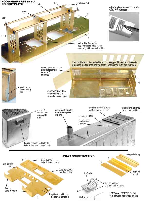
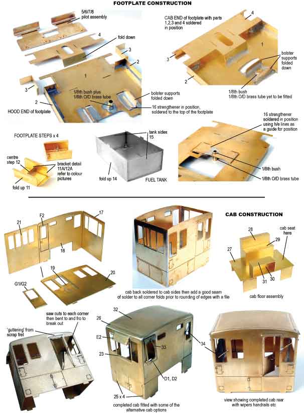
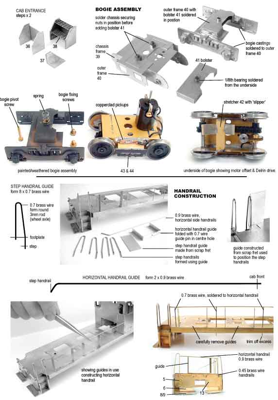
Half etch is abbreviated to h/e in the text. Kit includes: MOTOR BOGIES Take the outer frames 40 and fold down sides. Offer up chassis 39 and secure with the two short 6BA nuts and screws. Ensure chassis is central in frames and solder nuts in position then remove chassis from outer frames. Take bogie bolster 41 and fold down sides. Solder a 1/8th bearing from the underside then solder the unit to the half-etch on top of the outer frames 40. If using Slaters wheels remove extended pinpoint axles flush with the front face of the wheel by use of a piercing saw or slitting disc. Temporarily fit the wheels to chassis 39 and fit chassis to outer frames. Clean any flash from bogie castings with a knife/scalpel blade and solder to frame sides, aligning with the wheels. When done remove chassis. Take a Mashima 14 x 24 motor and fit to chassis top
plate. Add a 1/8 axle and temporarily fit a Romford 40:1 gear set. Adjust
motor position on chassis top plate for the best gear meshing. Disassemble
and reassemble adding a Delrin sprocket to the gear axle. Refer to the
photos. Then add a sprocket to the rear axle aligning with that on the
front axle. Add the chain, splitting to the length required and joining
over one of the sprockets. Do not have the chain too tight, the system
works fine with plenty of slack. Again refer to the photographs for
the chassis construction. These show the motor offset with the Delrin
sprockets and chain. Generally Delrin sprockets are a very tight fit
to 1/8th axles, so do not force them on. It helps if you countersink
each end of the sprocket and carefully ream till they are a tight sliding
fit. Take your time with this, check frequently the fit. Should a sprocket
slip on the axle one can drill through and pin with brass rod. One may add the brake gear now between the wheels. Fold up part 43 and add h/e layer 44. Adjust so the assembly aligns with the wheel rims and solder in position on chassis side. Add pick-ups to chassis. Refer to the pictures. In this instance double-sided copper clad (rail sleeper) was soldered to the chassis sides between the wheels, then a length of pick-up wire was soldered to the copper clad, bearing on the wheel treads. Add wire from pick-ups to the motor and test run. Repeat assembly for the second bogie if desired noting that the motor shaft will need to be cut off the rear bogie with a slitting disc to clear cab floor. FOOTPLATE HOOD CONSTRUCTION Take pilot overlays 5 and before soldering to the front face of pilot 6 fold up the pivot supports and pass these through the slots in the overlay. Fold up step support on pilot. Optional vertical bracing bars B may be added to the pilot to ‘beef up’ the front end as seen in some prototype pictures. Add steps to the supports by folding up rear of 8 and to give steps thickness add 9 to top of 8. Note outer corners are rounded off. Add the horizontal handrails from 0.45 wire to front of pilot. Alternative holes are etched on rear, again prototype pictures show a variety of positions. Similarly, make-up uncoupling arms from 0.45 wire or 0.7 if you need them to be more robust. Another option is to fit the ‘wire plough’ between the steps 8/9. Take frame 10 and fold up semi-circle. Ream holes for easy fit and bend up lengths of 0.45 wire and solder in position. It does not matter if they are over length. When they are all soldered in position they can be clipped and filed flush. Using the three half-etch dashes for alignment, it can be soldered to the rear of the pilot between the steps. Final detail to be added is the hose bracket 13 to the right of the coupler pocket. Leave adding the cast hose till the final detailing stage to avoid damage. Pilots may now be soldered to the underside of footplate against the valances 3. Fold up coupling mount 7 and decide which hole to use for Kadee coupler 805. It depends how far you wish the coupling to extend to clear ‘wire plough’ if fitted. Whichever you choose, solder coupling secure nut to part 7 before soldering to slots in 8. Remember one will have to cut/file off side mounts on coupling to enable it to pass through the slot in the pilot. Fold up step assembly 11 as photo. Add middle steps 12. Bracket detail 11A and 12A may be added. This can be soldered in position or stuck in place with cyno or similar glue at the final assembly. Having made up four such units they may be attached to the cut out on the underside of 4. Solid steps may be substituted with grill variants cut from etch B. Fold up fuel tank 14 and add sides 15. Check fit to slots in footplate but do not solder in position. Detailing the pilot, coupling lifting arms etc can be formed from 0.45 brass wire and added in the final stages. HOOD CONSTRUCTION Using the footplate to assemble the hood frame, tack solder 45R to the rear slots 46m to the middle and 47F to the front. Ensure all three are aligned and vertical. Use a minimum amount of solder (use low melt), as you want to be able to remove the assembly easily. Add central stretcher 48, solder in position flush with the top of frames. Take 2.5mm brass rod, and solder to circular cut-outs in corners of frames and ensure rod is shorter than the central stretcher. It is only there to assist in forming sides. Take louver panels 49 and 50 and offer up to the hood wrapper 51. Check orientation and then with tweezers fold each louver to approximately 20 degrees. When done, carefully align and solder in position. With a pencil/scalpel blade mark centre line on the underside of hood, this will align central stretcher. Do not forget to form the rivet detail. Unsolder tack joints and remove the hood frame from the footplate. At this stage bend the curve on the hood front – see photo. The framework can now be placed on the underside of hood wrapper, aligning with the centre line and parallel to the half-etch fold lines on the sides. Before tack soldering, check rear edge of central spacer aligns with rear edge of hood. Solder in position. Place assembly on a hard surface, say a cutting mat, and ‘roll’ sides into position. Tack solder. Similarly, bend round hood front, add a good fillet of solder to seam on hood front/sides – check fit to footplate before adding any other detail to hood. Round off edges and corners with a file and polish with emery. Fold down edges of radiator grill cover 52. Solder along seam for strength then file back to half thickness and solder to half-etch lines either side of the grill on hood top, either open/shut or in between. Cast exhausts can be bought from American sources P&D etc. or one can use the oval tube provided and solder over grill on hood top. The hood hinges, double doors 55D and single door 54S can now be soldered in position or left till later and put in place with a spot of Superglue. Form hood door handles from 0.45 wire. To get them all the same size use the etch guide provided. To use, bend wire to 90 degrees then pass through hole. Lay the wire in the half-etch line and trim off at edge. If you want a handle with a slight curve to the end, bend round slightly before trimming. The small guide is for cab door handles. Add panel 53 to hood top, hinges same side as exhaust. If fitting handles from 0.45 wire, drill out half-etch holes on underside of panel. Half-etch corners on hood top locate panel. Only item now to be fitted is the choice of lamp unit for the hood front. Originally fitted with the large round variety but later models fitted with the twin lamp rectangular unit. Note the round cast light units provided also have the option of fitting two small lenses, another modification done on a number of prototypes. Add Scala lens or similar to your chosen castings or drill out and fit working lights. Note one of the rectangular lamp casting is angled to allow for the slope on the hood front. Optional lifting rings C were fitted to the bonnet sides on a few locomotives. BACK TO THE FOOTPLATE Having assembled motor bogies, check for bogie swing by securing to the footplate and filing away bogie bolster as necessary. Whilst dealing with the footplate remember at some stage to fold down cast air tank supports. Cast tanks fit centrally in the width and add the cast air pipe to each tank. The fuel tank assembly can be filled with ballast weights and fitted at the final stages. THE CAB Begin with the basic structure. Take cab etch 17 and carefully fold round sides. Take brass rubbing, using a soft pencil, of window apertures on overlays 16 and 20. These will be your guides for trimming the glazing (not supplied). It is best to cut the glazing at this stage before the cab is completed. Solder the overlay 20 to inside face of the cab front 17. Do the same to the cab rear 19 using part 18. The cab rear then butts up to cab side and the whole unit will fit to the slots in footplate. Ensure there is a good seam of solder as all edges are to be rounded off with a file. Also at this stage open out holes in cab panels for handles, handrails and window wiper pivots if fitting. Caution, do not finally fit the cab until it is painted and glazed. If modelling cab with rear door open you may find it easier to do prior to soldering cab rear to cab sides. Refer to photos but procedure is similar for both doors. With a piercing saw or slitting disc, cut across door to be removed to each corner then carefully bend along half-etch line of door outline and snap out. Clean up opening and solder door in chosen open position having soldered inner door F2, G2 to outer door F1, G1 and made up door handles from 0.45 brass wire. With the cab rear soldered to the cab sides, trial fit to the slots in footplate. Fold up floor 27 and position in cab (you will have to position it first if you have modelled the rear door open). Tack solder floor in position on footplate. Fold up the control panel 28 and add top 29. Fold up cupboard/seat 30. Add top 31. Position these through the open cab roof and mark position on floor with pencil. Remove cab and solder in position. Add a representation of the control handles by soldering the two handrail knobs to the control panel top and adding short lengths of 0.7 brass wire for the handles. Fold up seat 35, solder to a length of brass rod and position under cab side window. Fold over top edge of cab sides then take cab roof 32 and gently bend between finger to match cab profile. Roof rests on overlays between cab front and rear. Solder in position. With a file round all edges – refer to model photos. Take time to get even curvature and corners, polish with emery. Similarly, blend in cab side to the roof. Roof rain strips 26 can now be added. With all cab edges rounded off, any additional detail may now be added ie. Long/short cab side window visors E1/E2. Cab side window may be added in the closed position 21 or open 22. If fitting window wipers, straight variants 34, drill out holes to accept a short length of 0.45 wire on which to mount wiper arm. Twist end of arm through 90 degrees before soldering in position. If fitting wiper to cab front door remember to shorten wiper blade, as window is narrower. There is an option included which is an ‘opening’ engineers cab front window (2 parts D2). If fitting, solder hinge cover h/e to the h/e on top of window and solder to cab front, flat against cab or as in photo set with a small gap at the base. A small stub of 0.45 wire soldered from the inside prevents it closing. Add one of the cranked wipers 33 to short length of 0.45 wire. Remember the rear cab entrance handrails from 0.45 wire, use the etch guide. A cast roof vent is included. Cast horn may be added to cab front, roof or hood top, making a loop of 0.45 wire to support the horn. Soldering a thin piece of fret off cut to the half-etch line and filing back can enhance rain strips h/e above cab doors. A representation of marker light bracket can be had using parts 56. Solder to top corner of cab side, similarly, combine two circular parts 56 and position beneath brackets to represent the electric socket. Make up and fit from 0.45 wire the handles for the cab side locker doors, plus add the cab side door hinges 25 to the half-etch recesses. Add handrails to rear cab door entrance from 0.7 wire using etch guide. Finally add chosen light casting to cab rear. Make up the steps for cab front and rear entrances. Take frame 36 and fold round sides. Add side overlays 37. Carefully trim out step grills 38 and fit to half-etch horizontal lines. Add cab body to footplate and position the steps front and back, mark position with a pencil then remove the cab and solder step units to footplate. At this stage it is probably best to loosely fit hood and cab to the slots in the footplate. Add the motor bogies and coupling to choice and test run round your favourite layout/test track making any clearance adjustments before fitting handrails etc. HANDRAILS Take the footplate and ensure all the vertical handrail holes accept 0.7 wire. Similarly do the same to holes in cab front but to accept 0.9 wire. Note: one can add the optional handrail detail to the footplate (triangular) and cab (single bolt). Ream so these items are a loose fit on the handrail wire. They can be secured with solder or a spot of cyno glue after all the handrails are in position. Items are not fitted to the model in the photos. Fold up the two etched handrail guides and add a short length of 0.7 wire to the centre hole, file back so it is just proud. Tack solder with ‘low melt’ to the edge of the footplate, see photo. Then take a length of 0.9 wire and fold and trim as the diagram to make the horizontal handrail. Pass through the hole in cab front and resting it on the semi circular cut outs on the two guides adjust the angled end then solder to the rear upright on the step handrail. The next step is to pass lengths of 0.7 wire up through the holes in the footplate and solder to the 0.9 horizontal handrail. Solder every other one to the footplate before removing the guides from the footplate. For the end handrails just use one of the guides. Trim and rest a length of 0.9 wire on the guide between the step handrails and solder in position. The guide can then be sprung out without damage. The last handrails to add are the long horizontal items formed from 0.45 wire that run across the footplate at the top of the pilot. At this stage bring all the elements together, adding any castings/detail you wish to personalize your loco. Now head for the paint shop then get shunting! |
Back to the 2 DOORS DOWN page